Goals
- Understand what an LED is and why it needs a resistor.
- Wire an LED to the Arduino Nano and make it blink.
- Learn what each line of the Blink sketch does.
Necessary components
- Arduino Nano (or compatible) —
- LED (any color) — 1
- Resistor 220 Ω (or 200–330 Ω) — 1
- Breadboard and jumper wires — a few
- USB cable to connect Nano to your PC
Note: The Nano also has a built-in LED connected to digital pin 13. You can test using that without wiring any external LED.
What is an LED and why the resistor?
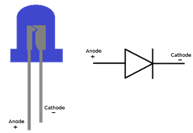
An LED (Light Emitting Diode) is a semiconductor that emits light when current flows through it in the forward direction. Important properties:
- Polarity — LED has anode (positive, longer leg) and cathode (negative, shorter leg). Current flows anode → cathode.
- Forward voltage (Vf) — voltage drop across the LED when conducting. Typical Vf: red ≈ 2.0 V, green ≈ 2.0–2.2 V, blue/white ≈ 3.0–3.3 V.
- Desired current — how much current you want through the LED. A typical safe choice for a single LED from an Arduino pin is 10–20 mA (0.01–0.02 A). Aim for 10–15 mA for bright but safe operation.
Why resistor? The microcontroller pin provides a fixed voltage (5 V on a Nano). Without a resistor the LED would try to draw unrestricted current and either the LED or the pin (or both) could be damaged. The series resistor limits current.
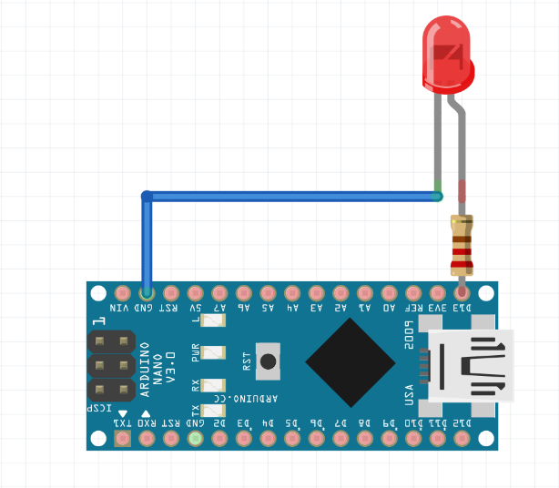
- Digital pin 13 → 220 Ω resistor → LED anode (long leg)
- LED cathode (short leg) → GND (Arduino GND)
Important points:
- Always use a resistor in series with the LED.
- Make sure grounds are common (if using external power).
- If you accidentally connect LED reversed it simply won’t light (no damage if resistor present).
Code:
void setup() {
 pinMode(13, OUTPUT);
}

void loop() {
   digitalWrite(13, LOW);
   delay(1000);
   digitalWrite(13, HIGH);
   delay(1000);
}
Step-by-step code explanation
This sketch repeatedly turns the LED on and off, with each state lasting one second (1000 milliseconds). setup() runs once when the board boots; loop() runs over and over.
- This particular sketch uses pin 13 directly (the built-in LED is connected to D13). Using the numeric literal 13 is okay, but later we’ll show a better style using LED_BUILTIN.
void setup() {
 pinMode(13, OUTPUT);
}- void setup() — this function runs once when the Arduino resets or powers on. Use it to configure pins and initialize libraries.
- pinMode(13, OUTPUT); — configures digital pin 13 as an OUTPUT. That means the pin will actively drive voltage (HIGH ≈ 5 V, LOW ≈ 0 V) rather than being an input. If you forget this, digitalWrite() may not behave as expected.
void loop() {
   digitalWrite(13, LOW);
   delay(1000);
   digitalWrite(13, HIGH);
   delay(1000);
}- void loop() — runs repeatedly after setup() Everything inside loop() will execute forever.
- digitalWrite(13, LOW); — sets pin 13 to LOW (0 V). For the wiring described above, this turns the external LED off. (If the LED is wired to Vcc through a resistor and the pin sinks current instead — a different wiring — the meaning of LOW/HIGH is inverted. By standard wiring pin → resistor → LED → GND, HIGH lights the LED.)
- delay(1000); — pauses program execution for 1000 milliseconds (1 second). During delay(), no other code runs.
- digitalWrite(13, HIGH); — sets pin 13 to HIGH (approx 5 V). This turns the LED on.
- delay(1000); — pause 1 second while LED remains on.
So the sequence inside loop() is: off 1s → on 1s → repeat.
NOTE about order: your sketch writes LOW first and then HIGH. That means after uploading the program the LED will first be set to OFF for 1 second, then ON for 1 second. That ordering is fine — some examples set the LED HIGH first; it’s just start-phase behavior and does not affect the repeating blink pattern.
What HIGH/LOW actually mean:
- HIGH = microcontroller outputs ~5.0 V (on most Nanos running from USB).
- LOW = microcontroller outputs 0.0 V (GND).
The external LED, connected from pin → resistor → LED → GND, lights when pin is HIGH.
About the delay() function
delay(ms) stops the CPU from doing anything else for ms milliseconds. That makes this example very simple — but if you later want to do multiple tasks at once (read sensors while blinking), you should learn the millis() non-blocking timing approach (covered in Lesson 5)
Troubleshooting & common mistakes
- Nothing lights up
- If using built-in LED: make sure sketch uploaded successfully and Tools → Board/Processor/Port are correct (Lesson 1).
- If using external LED: check resistor and LED orientation (anode to pin, cathode to GND).
- Try replacing the USB cable (many cables are charge-only).
- LED always on or always off
- Check wiring and pin number. If you wired LED between 5V and pin (instead of pin and GND) then logic is inverted (pin LOW will light it because pin will sink current).
- LED is dim or very bright
- If too bright: use a larger resistor (330 Ω). If too dim: use smaller resistor (e.g., 150 Ω) but stay under ~20 mA
Safety & electrical limits
- Do not draw more than ~20 mA from an Arduino I/O pin continuously. Absolute max is typically 40 mA but that risks damage. Use transistors or MOSFETs to drive bigger loads or multiple LEDs.
- When using many LEDs, use a separate power supply and common ground, or use driver chips (e.g., shift registers, LED drivers).
Extensions / exercises
- Change both delays to different values (e.g., delay(200); delay(800);) to make an asymmetric blink.
- Use two LEDs and alternate them (one ON while the other OFF).
- Replace delay() with a millis() timer so you can blink while reading a sensor. (Practice for Lesson 5.)
- Use PWM (e.g., analogWrite(pin, value)) to fade the LED up and down. Note: analogWrite works only on PWM pins (3, 5, 6, 9, 10, 11 on Nano).
Checkpoints / tests (pass/fail)
- Upload success: serial console shows Done uploading and code runs.
- If using built-in LED: LED blinks 1 second off, 1 second on, repeatedly.
- If using external LED: verify wiring and LED blinks with the same pattern.
- Measure pin voltage with a multimeter: when LED is HIGH the D13 pin should read ≈5.0 V; when LOW ≈0.0 V.