Introduction
We all remember those moments from childhood—the excitement of opening up a toy to see what’s inside, the satisfaction of building something with our own hands, and the endless curiosity that made us ask, “How does this work?” That natural curiosity is the foundation of innovation. The purpose of the Robo Starter course is to nurture that curiosity and transform it into real skills. This course is not just about learning electronics or programming; it is about empowering you to turn your imagination into real, working technology.
At the heart of your learning journey is Arduino, a powerful and beginner-friendly microcontroller platform used by students, engineers, and innovators around the world. Think of Arduino as the “brain” of your projects. It receives information from sensors, processes that information based on your program, and then controls outputs such as lights, motors, and displays. Understanding Arduino will give you a strong foundation in embedded systems, robotics, and future technologies like IoT (Internet of Things) and automation.
To make programming simple and accessible, this course uses PictoBlox, a visual programming environment developed by STEMpedia. Instead of writing complex code, you will use colorful, drag-and-drop blocks to create programs. This block-based approach allows you to focus on logic, creativity, and problem-solving without worrying about syntax errors. As you progress, you will naturally develop computational thinking skills—the same skills used by professional software developers and engineers.
This book is carefully designed to guide you step by step, starting from the very basics. You will begin with simple projects such as controlling an LED, understanding buttons, and reading sensor data. Gradually, you will move on to more advanced and exciting systems like smart automation projects, weather monitoring stations, solar trackers, and intelligent robotic applications. Each chapter follows a structured approach:
This learning-by-doing approach ensures that you do not just memorize concepts—you understand them by building real systems. Most importantly, you will shift from being a technology user to a technology creator.
This is your first step into the world of robotics, embedded systems, and intelligent machines. The journey may challenge you at times, but every challenge will make you stronger, more capable, and more confident.
So now, it’s time to begin your journey.
Are you ready to build, experiment, and create the future? Let’s get started
What Is a Microcontroller?
A microcontroller is a complete, miniature computer on a single chip, or integrated circuit (IC). It contains a processor to execute commands, memory to store data and instructions, and input/output (I/O) pins to interact with the world outside the chip. Unlike a traditional computer, which is designed for multiple tasks, a microcontroller is a specialized device built to perform specific functions. These functions can include controlling a machine, processing data from a sensor, or automating a device.
The “brain” of an Arduino board is its microcontroller (e.g., the ATmega328P on the Arduino Uno). This chip is responsible for processing all the instructions you write in your program and turning them into real-world actions.
Introduction to Arduino
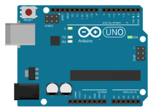
Arduino is a globally popular open-source electronics platform that simplifies building interactive projects. It’s built on user-friendly microcontroller boards and a programming environment designed for beginners. With Arduino, you can easily connect components like sensors, motors, and lights to create prototypes, automate tasks, or bring innovative ideas to life.
By combining accessible hardware and software, Arduino has become a go-to tool for students, hobbyists, and professionals in fields like electronics, robotics, and the Internet of Things (IoT). The platform offers versatility by supporting both block-based coding (with tools like PictoBlox) for new users and C/C++ programming for more advanced users.
Key Features of Arduino:
- Open-Source Hardware and Software: Both the designs and code are freely available and driven by a large, collaborative community.
- Affordable and Versatile: Suitable for a wide range of projects, from simple DIY creations to complex systems.
- Wide Compatibility: Works with thousands of sensors, actuators, displays, and IoT modules.
- Cross-Platform: The software runs seamlessly on Windows, macOS, and Linux.
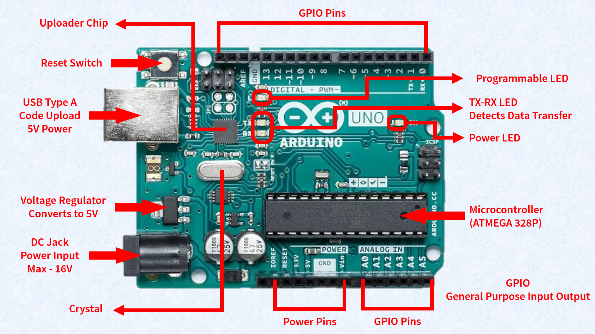
Arduino Board Anatomy
An Arduino board is composed of several key parts, each with a distinct function.
- Reset Button: Restarts the program currently running on the board.
- USB Port: A multi-purpose port used for powering the board, uploading programs, and enabling communication with your computer.
- Power Jack: Allows you to power the Arduino using an external adapter, with a recommended voltage range of 7V to 12V.
- 5V Regulator: This component provides a stable 5V supply to the board and its components. It safely converts higher input voltages (7V–12V) down to the required 5V, protecting the board from damage.
- Crystal Oscillator (16 MHz): This component provides the crucial clock timing for all operations on the board, ensuring that instructions are executed precisely.
- Microcontroller: The brain of the Arduino (e.g., ATmega328P). It processes all the programmed instructions, reads sensor data, and controls the input and output pins.
- Power LED (ON): A small LED that illuminates when the board is receiving power, confirming that the circuit is active.
- Built-in Programming LED (L): This LED, connected to digital pin 13, blinks automatically during program uploads to indicate communication. It can also be controlled by your code for debugging and testing.
- TX LED (Transmit): Lights up when the Arduino is sending data to a computer or another device via the serial port.
- RX LED (Receive): Lights up when the Arduino is receiving data from a computer or another device via the serial port. Both LEDs are vital for monitoring serial communication.
- TTL Converter / Uploader Chip: This chip manages serial communication between the microcontroller and the computer. It translates USB signals into TTL (Transistor-Transistor Logic) signals that the microcontroller understands, making the program upload process safe and reliable.
- Digital Pins (0–13): These pins are used for sending or receiving HIGH (ON) or LOW (OFF)
- Analog Pins (A0–A5): These pins read variable signals (0V–5V) from sensors, allowing you to measure things like temperature or light intensity.
- PWM Pins (~3, 5, 6, 9, 10, 11): These pins are capable of Pulse Width Modulation, which simulates an analog output and is used to control devices with variable power, such as adjusting the brightness of an LED or the speed of a motor.
Arduino Pin Configuration (Arduino Uno)
A. Digital Pins (0–13)
These pins can be configured as either inputs or outputs.
- As outputs, they can send digital signals (HIGH = 5V, LOW = 0V) to turn devices like LEDs or buzzers on or off.
- As inputs, they can read HIGH or LOW signals from components like switches or digital sensors.
B. PWM Pins (~3, ~5, ~6, ~9, ~10, ~11)
These are special digital pins that support Pulse Width Modulation (PWM). This technique simulates an analog output by rapidly switching the pin between HIGH and LOW. By changing the duty cycle (the percentage of time the signal is HIGH), you can control the output level.
- Example: Setting a PWM value of 128 (out of a 0–255 range) on a pin will make an LED glow at approximately half brightness.
C. Analog Pins (A0–A5)
These pins are designed to read analog signals, which can vary continuously. The Arduino uses an Analog-to-Digital Converter (ADC) to convert the analog voltage (0V–5V) into a digital value ranging from 0 to 1023.
- Example: Reading the temperature from an analog sensor or the light intensity from an LDR.
D. Power Pins
- 5V and 3.3V: These pins provide a stable voltage supply to external components and sensors.
- GND (Ground): The common reference point for all circuits on the board.
- VIN: This pin allows you to power the Arduino using an external supply (7V–12V).
E. Communication Pins
- TX (Transmit) and RX (Receive): These pins are used for serial communication with a computer or other devices. TX sends data, and RX receives data.
- SDA (A4) and SCL (A5): Used for I²C communication, which allows the Arduino to communicate with multiple devices using just two wires, a major advantage for complex projects.